FreeMASTER is a useful tool developed by NXP to perform debugging, logging, and tuning of control algorithms. This guide will cover using the sample software for accessing controller memory through the CAN bus.
WARNING: Accessing controller memory can cause unsafe conditions if not done safely. This tool should be used for development purposes only, and not for production firmware deployments.
Prerequisites
- Install FreeMASTER from NXP website (latest version 3.2 as of Nov 2025)
- Install the Audesse Simulink library from downloads (latest version 2.0 as of Nov 2025)
Configure the CAN Connection
- From the Audesse sample_models folder installed previously, make a copy of FreeMaster_over_CAN_k3.slx in your chosen working directory.
- Open the sample model, build and flash to the FlexCase
- Connect the PCAN-USB hardware connected
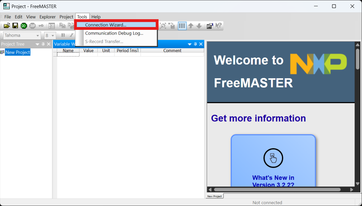
- Start FreeMASTER and run the Connection Wizard tool in the Tools Menu or by clicking the box in the main project page
- Enter the following options:
- Port Type: CAN Bus
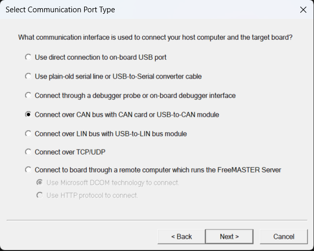
-
- Click “Plug-in Configuration” to establish the connection
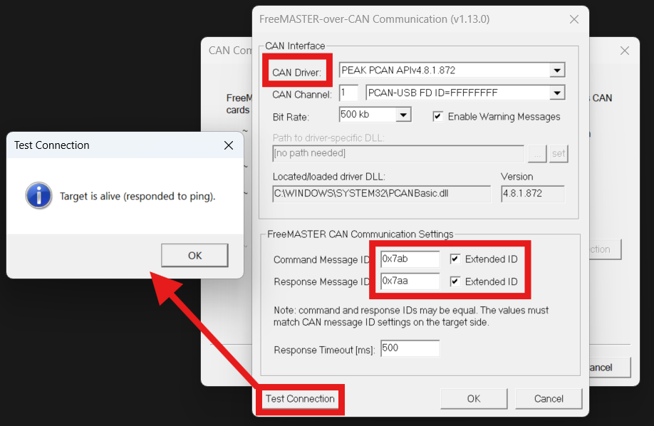
- Driver: PEAK PCAN
- Command ID: 0x7ab extended
- Response ID: 0x7aa extended
- Click “Test Connection”
- A popup will indicate that the board is connected
- Click “Finish”
- Click “Plug-in Configuration” to establish the connection
- The software will prompt you to load symbolic information, or if you are returning to a previously saved FreeMASTER template, you can click Project>Options>MAP Files from the main men:
- Under Default symbol file: Add the FreeMaster_over_CAN_k3.elf that was generated in the Simulink build.
- Depending on the prompts, the connection to the board may start automatically, or you can toggle the connection with the GO/STOP buttons at the top of the menu

WARNING: Do not attempt to connect to the board while flashing new software, or attempt to flash software while FreeMASTER is connected. Always click STOP before using the PCAN hardware for other purposes.
Read Model Data Variables
- Start the connection to the board if not already started
- In the “Variable Watch” area at the bottom of the page, select “Create new watched variable”:

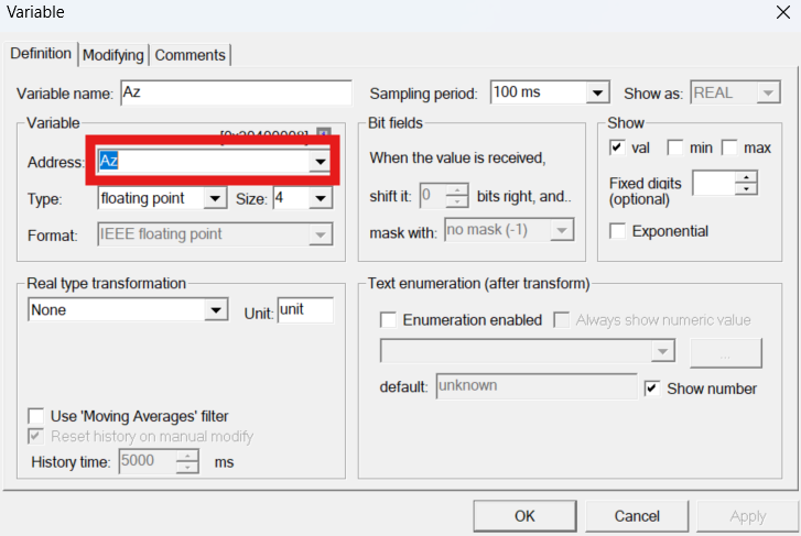
- Select the variable Az (vertical component of acceleration) in the “Definition” tab. Leave the “Modifying” tab as is for now.
- Click the Address drop-down and start typing the name, and other properties will be updated when the variable is selected*
- Make sure the type matches the definition in the Simulink model (a single is a 4-byte floating point number)
- Set the sampling period for preferred time resolution.**
- If formatted correctly, you should see the variable changing as the FlexCase moves and tilts
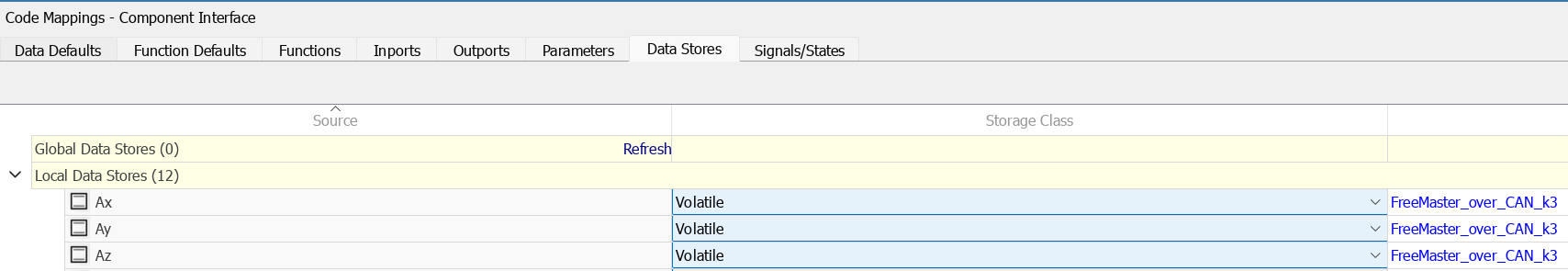
*Variables used in this sample are formatted as “Volatile” in code mappings for ease of debugging, but generally the storage classes should be set back to default for production releases of software
**When you are developing your own projects, reading many variables at the “fastest” polling speed may cause bottle-necks, so only select fastest polling for variables that require it, and select an appropriate timing interval for others.
Write to a variable
WARNING: Writing directly to data has the potential to cause damage or unexpected behavior, and should only be done in the development phase of your project. Take extra care to ensure that the variable properties (size, type, min/max) match between the model and FreeMASTER.
- Create a new watched variable for LED_on:
- 1-byte unsigned (boolean)
- Sample time 1s (written variables will update immediately when user enters new value)
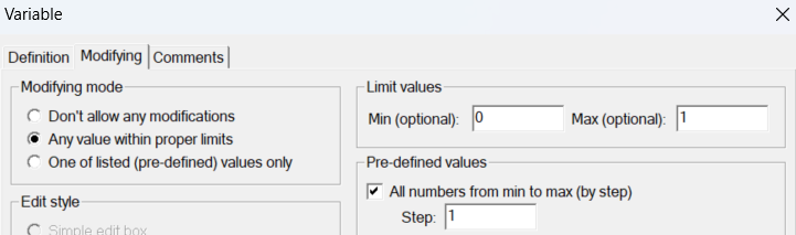
- In the Modifying tab, allow any value within limits 0 to 1 and allow predefined values. This setting is important to consider to prevent unexpected behavior.
- Toggling this boolean will activate and deactivate the external supply, which is usually connected to an LED switch with FlexCase prototyping kits. If connected in the wire harness, the switch LED should toggle along with the boolean in FreeMASTER.
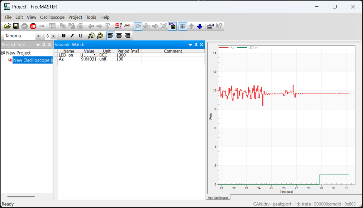
View and Log Polling Data
Create a new Oscilloscope from the Project Tree and insert the input and output variables:

- Set the period to 10ms
- In the variables tab, add LED_on and Az. Similar variables can be placed in the same block, or you can create multiple blocks for multiple Y-axes
Logging is available via the Oscilloscope properties.
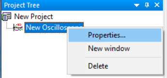
In the Data Capture tab of the Oscilloscope properties, select the following:
- Capture data on background (logging whenever connected to the board)
- Recording starts always to new file
- Text format
- Create a destination directory for each session or project iteration, since the file names generated are generic (osc0001.txt, etc.)
- Change capture mode back to “Data capture off” so that capture can be manually switched from the main toolbar.
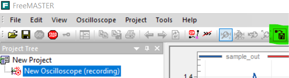
After connecting to the board, you should be able to toggle the recording setting and see new logs being generated in your chosen directory:
The different available logging options will depend on your specific application. Multiple oscilloscopes can be set up and recorded with different default settings for recording.
HTML GUI Elements
FreeMASTER is capable of rendering arbitrary HTML/JS to add more flexibility to the user. When adding functionality, always avoid using html/javascript templates or libraries from untrusted sources.
Download the HTML GUI sample from our sample software page. The archive contains the following files:
- example_flexcase.htm : base html page
- freemaster-client.js : NXP library for interfacing the html page with FreeMASTER
- simple-jsonrpc-js.js : connection for browser renderer
The unmodified version of the files can be found at the FreeMASTER installation path if needed
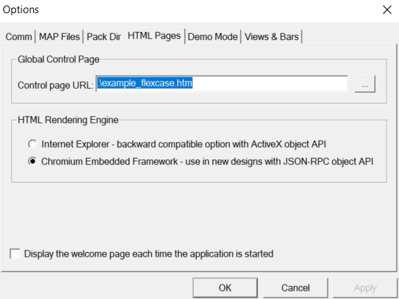
Unzip the archive and point to the HTML file in the FreeMASTER options. Make sure the rendering engine is set to Chromium/JSON-RPC.
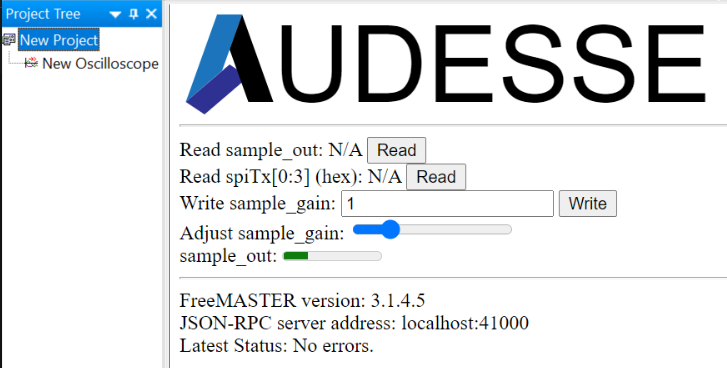
The main project area should now show some basic html elements. If the page does not display immediately, press F5 to refresh the page. The FreeMASTER functions for reading/writing variables can be connected to generic display elements.
Next Steps
After completing this tutorial, you should be familiar with the basic functions available for debugging, logging, and calibrating your software during development. The HTML sample can be used to create custom testing/calibration interfaces.
The data is not guaranteed to be synchronized with the execution loop of the processor. Other options are available to capture logs for debugging or analysis, so please let us know if your project has special requirements.
Adding other variables with “Volatile” storage class is useful for debugging, but should be reverted to default when releasing production software.