
FlexCase
Simulink RPI MPU Setup
- Install and configure the Simulink support package for Raspberry Pi
- Configure a Simulink model to build onto the FlexCase
- Build a simple model to the FlexCase

The onboard Linux computer can be used as a secondary source of processing power. There are a multitude of ways to utilize the computer, including running standalone Simulink programs in parallel with the MCU.
This guide is more advanced than the basic tutorials, so please contact us if you have additional questions before proceeding.
Prerequisites
- This tutorial assumes that you have purchased a FlexCase with the Pro version, which includes can be configured with an onboard Raspberry Pi computer (Guide not applicable for Rockchip based platforms)
- Complete the quick start guide for a tutorial on connecting to the FlexCase and flashing binaries
- Complete the Simulink guide for building a model into a binary
- Complete the SSH connection guide
Install Support Package
- Open MATLAB Click on “get add-ons” from the main menu
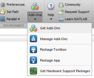
- Install the add-on “Simulink Support Package for Raspberry Pi Hardware”. The support package for MATLAB will also be included in the installation

- DO NOT configure or set up the add-on once installed. More Info
Configure Simulink Model
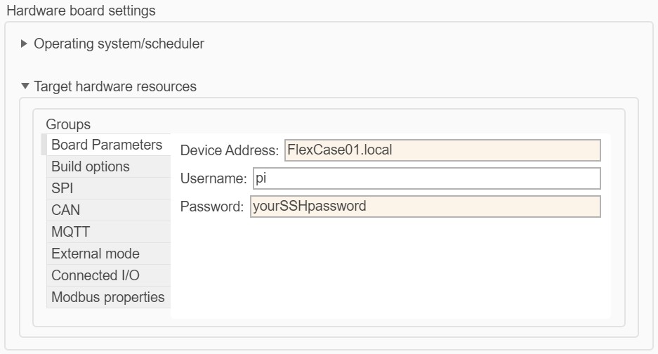
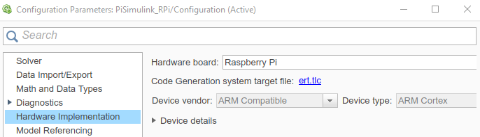
Open the provided model MPUBasics.slx from the software downloads section. Once loaded open Hardware Settings/Hardware Implementation in Simulink and configure the model for your simulation.
| Hardware board | Raspberry Pi |
|---|---|
| Device Address | yourHostname.local |
| Username | pi |
| Password | your SSH password |
| Build Action | Build |
| Build Directory | /home/pi |
| Run on Boot | No (uncheck) |
| SPI0 CEO Bus Speed (kHz) | 4000 |


Build and Run the Model
While connected to the FlexCase, you can run the RPi model in external mode for quick design iterations. Ensure that the communication interface is set to “TCP/IP” and not “XCP over TCP/IP” for scopes and data displays to function.
Change the Stop Time to inf and press Monitor & Tune to run the model on the FlexCase through the Simulink interface. For older versions of Simulink

We can see the model running by opening the scope and observing the incrementing value. Simulink may also indicate that the model is running with a “Running the model on Raspberry Pi” notification in the lower left corner.
Success!
You have successfully connected Simulink to the MPU for external mode simulation. You can now begin adding your custom applications to the FlexCase. We recommend reading how to do MCU co-processing below.
Next Steps
Once you are happy with your code development, you can deploy the code to the MPU to run without PC attachment.
Build and Manual Run
You can build and transfer the file to the Pi to run manually by pressing Build. This will use the MATLAB coder to convert the Simulink model into C code, transfer the files to the Raspberry Pi over Ethernet and build the code into an executable binary.
If the previous step is performed correctly, MATLAB will create a workspace folder in the /home/pi directory. Inside this directory, there will be a copy of the folder structure present on the host machine.
For example if you saved the Simulink models to C:/FlexCase/Simulink on the host machine, there will be a /home/pi/MATLAB_ws/”matlab_version”/C/FlexCase/Simulink/ folder created on the FlexCase. To run this code:
- In terminal, navigate to the created folder using cd (to save some typing, you can press tab and the terminal will attempt to autocomplete partial folder names)
- Confirm that the compiled binary “yourProject”.elf exists in this directory using ls, where “yourProject” is the name of your file.
- Run the binary with the following command:
You can stop the model from running using CTRL+C in the terminal.
Build and Automatic Run
You can build and transfer the file to the Pi to run manually by pressing Build, Deploy, and Start.
This will complete all the steps in the previously described Build and Manual Run section, in addition to automatically starting the executable. The program will stay running until manually cancelled or a new version of the model is built. This option is generally not recommended since it can create multiple instances of the model running at once. If multiple instances of the model are started, you can power cycle the FlexCase to restore normal behaviour.
There is an option to run the built model automatically whenever the FlexCase boots up, which can be enabled by clicking the “Run on boot” checkbox in the model configuration. This option is not recommended until your model is sufficiently developed: running an unpredictable program automatically cannot be undone by the user until SSH is established, which may cause the RPi to become inaccessible.
In order to control the I/O on the FlexCase you will need to communicate with the MCU, which is done over SPI. The setup to do MCU Co-Processing is as follows.
Step 1 – Setup SPI
In order to communicate with the MCU you will need to enable SPI communication. This is achieved by modifying the default SPI settings. This should be done BEFORE the first time you build/run a Simulink model on the MPU that uses SPI to avoid incorrect build files being transferred.
Navigate to the support package source files and open the MW_SPI.c source file (your specific directory may differ depending on your MATLAB installation. Some example locations below):
example1: C:/ProgramData/MATLAB/SupportPackages/R2019a/toolbox/target/supportpackages/raspberrypi/src
example2: C:ProgramData/MATLAB/SupportPackages/R2021a/toolbox/realtimetargets/raspi/src/periphs
In the MW_SPI.c source file, change the default SPI_DEV_FILE definition /dev/spidev0. to /dev/spidev2. for CM3, or /dev/spidev1. for CM4.

This change will allow the FlexCase to use the non-default RPi SPI configuration to communicate with the MCU. The FlexCase compute module uses the SPI1/2 bus, whereas regular Pi’s use SPI0.
Step 2 – Setup Powerdown Routine (Optional)
The model PiSimulink_RPi.slx uses UDP packets to disable the default SPI configuration and allow the safe shutdown of the RPi via the Ignition (On/Off) switch. A simple script communicates with the UDP packets. If you do not use this feature, ensure that you power down the MPU safely.
- Establish SSH connection with the FlexCase (see python basics guide for details)
- Upload the udpShutdown.py and udpShutdown.service files to the FlexCase /home/pi directory
- Confirm upload by typing cd /home/pi/ into terminal, followed by ls
- Type the following terminal commands to set up the script to run automatically on boot:
If the Simulink model has been started and subsequently cancelled, this script will not restore the default safe shutdown behaviour. To make sure the Pi safely shuts down, you can either:
Option 1: Manually restore the default SPI communication after model is stopped (allows safe shutdown from ignition/off switch)
Option 2: Manually powerdown from terminal when you are ready shut off the FlexCase
Step 3 – Build Your Model
Communication between the MCU and MPU is done over SPI, so simply adding a SPI transfer block will work. By default, 64 bytes are sent per cycle, which for example can be captured using the approach show below.
![]()
For a complete example, please use the Co-Simulation Example found in the MPU samples.
This example assumes you have already completed the basic MPU Simulink guide and understand How to Use MCU in Co-Processing.
Opening the Co-Simulation Example in MPU samples.
For the MCU Code
- Move the model PiSimulink_MCU.slx to a suitable folder and open it, making sure the MATLAB current folder is set to the same location as the file.
- Build the model and flash the .elf file to the MCU (see Simulink guide for details)

This model will take input from a CAN message, send info to the MPU via SPI for processing, and then broadcast the resulting information on a separate CAN message. The spiMsg and spiRx blocks are used by a slightly modified version of the default SPI communication for the FlexCase MCU. The SPI transmission is split into 8 byte packets.
You can verify that the model is running by a CAN message with ID 0x333 being sent every 10ms. The data will be all zeros since the RPi is not currently sending any data to the MCU:![]()
For the MPU Code
- Ensure your model is configured correctly with parameters like the device address and password (Explained earlier in guide)
- Ensure that the SPI settings have been updated as explained in the previous section
- Press CTRL+B or click “Deploy to Hardware” from model menu
This will use the MATLAB coder to convert the Simulink model into C code, transfer the files to the Raspberry Pi over ethernet and build the code into an executable binary. This particular template shows the basics for communicating with the MCU over SPI. This model also uses a simple UDP connection to configure the default SPI communication on the FlexCase, and to shut off the Raspberry Pi if the Ignition (On/Off Switch) is turned off while the code is running.
Running the Co-Simulation
Navigate to the deployed code on your MPU, explained in How to Deploy Your Code and run the program
Verify that both the MCU and RPi programs are functioning correctly by sending test values on the 0x111 message, and seeing them be modified on the 0x333 message based on the calculations performed on the RPi:

- Taking the ignition state (either 0xAA or 0xBB) and adding 15
- Converting the FlexCase supply voltage coming in Millivolts across two bytes and converting to a single byte representing Volts (0x0C)
- Addition/subtraction/passthrough of the bytes on 0x111 message
- Writing of 255 (0xFF) to bytes 5 and 6
- A rolling count byte being incremented every cycle (10ms)

*The SPI channel is set to communicate 64 bytes of information per transfer, but only the first 8 bytes of the transfer are being manipulated in this example.
You can stop the model from running using CTRL+C in the terminal. Please note that the default SPI communication will not be restored when the model is stopped. To make sure the Pi safely shuts down by either restoring default SPI communications or manually powering down the MPU through terminal.
