
FlexCase
CAN Flasher
- Connect flashing wire harness
- Install flashing software
- Flash compiled code

Prerequisites (Windows)
- Ensure you have a PCAN-USB device, and that the device drivers are installed.
- Ensure you have bootloader software loaded on your hardware. Please contact us if you are unsure of your bootloader status.
- If applicable, uninstall previous versions of FlexCaseFlash at “C:/Program Files/flexCaseFlash/Uninstall flexcaseflash.exe”
Limitations
The CAN Flasher Rev 1.4.1 has the following limitations. Future revisions are planned to add features which remove these limitations.
- Tools are only compatible with MBDT 4.3.0 for S32K1 (FlexCase S / FlexBench) and with MBDT 1.4.0 or 1.7.0 for S32K3 (FlexCase E/G)
- For S32K1:
- The baud rate of the CAN bus which is used for flashing the bootloader is static. You will have to use the Pro version of the FlexCase hardware or a dedicated flasher to change the bootloader CAN bus baud rate.
- CAN0 Message Buffer 0 cannot be used for user functions (reserved for bootloader request message). Other message buffers on CAN0 and CAN1 are fully available for user functions.
- There is limited binary file checking implemented on the flasher. You will need to verify which version of MCU you have in order to flash the correct version. Attempting to flash the incorrect version will render the hardware inoperable until the bootloader is restored. See our guide on determining your MCU version here.
Assemble Hardware
Partial or full termination of the CAN bus is usually required for the devices to communicate.
FlexCase S / FlexBench
Connect CAN0 from the FlexCase to the PCAN-USB device, and connect the PCAN-USB device to your computers USB port.
Upon powering up, a low 0.5 second beep from the diagnostic buzzer indicates that the FlexCase has entered bootloader mode and is ready for flashing over CAN. The bootloader will also send a message over CAN every 5 seconds that indicates the hardware variant. The FlexCaseFlash program will also attempt to enter bootloader mode before flashing.
FlexCase E / FlexCase G
Connect CAN2 from the FlexCase to the PCAN-USB device, and connect the PCAN-USB device to your computers USB port.
Install FlexCaseFlash
- Uninstall any previous versions of FlexCaseFlash at C:/Program Files/flexcaseflash/
- Download the latest FlexCaseFlash archive from the software page
- Extract the archive, and run the setup to install the flasher. Use the default settings in the installer.
Flash a Pre-compiled File
- Click Open Project and select the folder C:/Program Files/flexcaseflash/resources/flashconfigs and then select the folder corresponding to your hardware.
- (Optional) For convenience, make a copy of the flxflashconfig file in the folder corresponding to your hardware, and move it to the folder where you will be generating or storing application binaries. This will allow edits to the configuration to be saved by the user.
WARNING: Selecting the incorrect hardware or modifying the project file will render the hardware inoperable until the bootloader is restored.
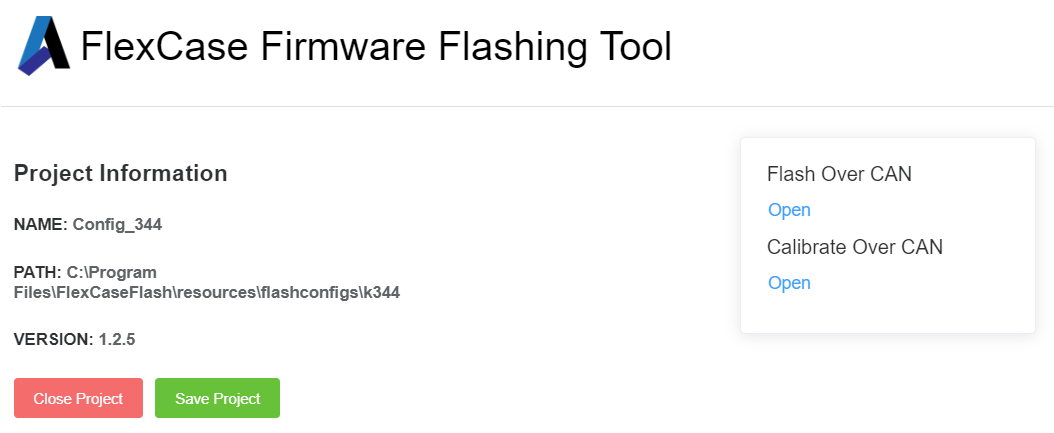
- Open the Flash Schedule on the right side of the project information screen.
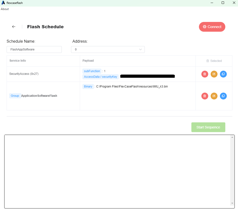
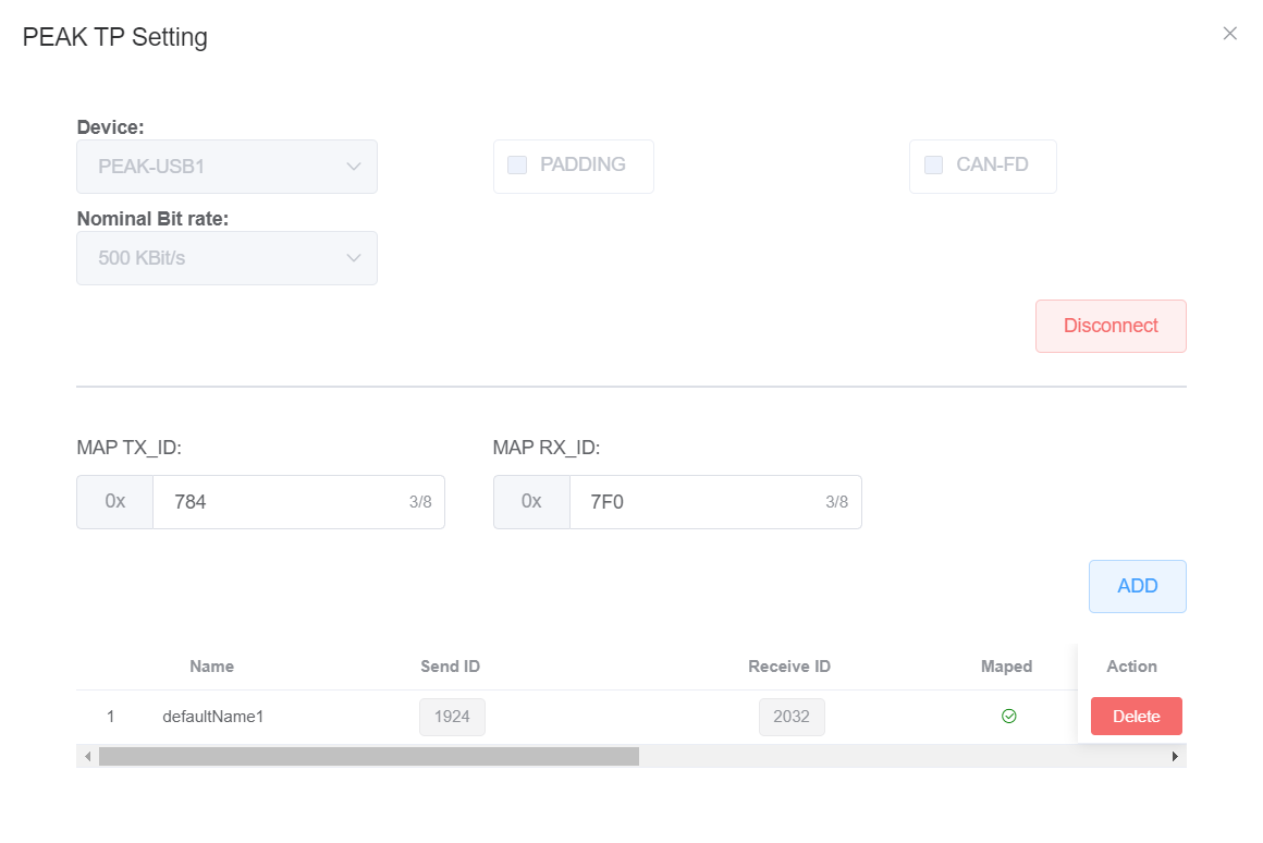
- Click the red Connect settings button at the top-right of the screen. In the popup, click Connect without modifying the default options and exit the popup. The settings button should now be green.
- Ensure that the binary file match your hardware. Invalid file paths display in red text, valid paths in black text.
- The first payload field is the default AES security key, which is tied to the bootloader software
- The second field is the application binary to be flashed over CAN.
Hardware-Specific: Flashing, Building, and Modifying Application Firmware
WARNING: Extra care must be taken when making changes to applications that will be flashed through FlexCaseFlash. If the hardware is rendered inoperable due to incorrect settings and you do not have a means of restoring the bootloader, your hardware will have to be shipped to Audesse for repairs at your expense.
- If making changes to sample models using Simulink, ensure that the following MathWorks products are installed: MATLAB, Simulink, MATLAB Coder, Simulink Coder, Embedded Code
- Choose the tab below corresponding to your hardware variant for further instructions
Building Application Firmware
A) Simulink
- Ensure that you have the K3 and Audesse toolboxes installed, see Simulink basics guide
- From the toolbox folder, make a copy IMU_k3.slx in a working folder of your choice.
- Open the model and ensure that extra configuration files are generated (this will take some time the first time the model is opened).
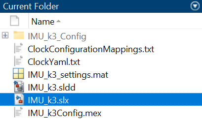
- Build the model with CTRL+B and ensure that the generated build includes a .bin file in the same working folder as the .slx model.
- At the end of the build, Simulink will attempt to send the binary to a target processor, which can safely be aborted to complete the build process.

B) S32DS
- If you don’t already have a S32DS project, download the S32DS Project Examples from the Downloads page and open the IMU_k3 project in S32DS.
- In the S32DS Project Explorer, select the project you would like to build, and then click the Build button in the toolbar.

- Wait for confirmation that the build has finished in the Console.

- The .bin file in the Debug_FLASH folder will be flashed in the next steps.

Flashing
- In FlexCaseFlash, click the orange Edit button next to the application binary, click Choose File to select the new path to binary you just built, click Change Group to apply changes.

- For the FlexCase E and G, the sample software will get data from the onboard IMU and broadcast the information over CAN2. It will also toggle the sensor supply output periodically, which can be connected to an external LED as an indicator.
- Power off the FlexCase and be ready to restart. On boot, the bootloader will stay active for approximately 1 second waiting for a flash request. If no application software is loaded or does not have enter bootloader functions, the Start Sequence button in FlexCaseFlash must be clicked immediately upon powering up the FlexCase.

- After a successful flash, the 5V sensor output will flash at 1Hz, and the CAN messages will be broadcast every 50ms. If you do not have a preferred CAN bus viewer software set up, you can use PCAN-View

Flashing
- For the FlexCase S, the sample software will periodically sound the diagnostic buzzer. Again, it is important to make sure the binary (142 or 144) matches your hardware.
- Click Start Sequence. The diagnostic buzzer will indicate entering bootloader mode with a low tone and the console will print out flash progress.

- After a successful flash, the buzzer should beep every 2 seconds, at a higher pitch than the bootloader indicator, and in shorter pulses.
Building Application Firmware
Modifications to your application software are required to function with the CAN bootloader. This section will cover modifications to Simulink models. Keep in mind that these modifications are not compatible with the regular flashing method, so only one can be used at once.
- Ensure that you have the MDBT installed, see the Simulink basics guide for detailed instructions

- Install our Simulink Library and follow the instructions in the readme file. If successful, the blocks will be installed and the NXP toolbox will be modified. The functionality being modified is:
-
- Custom source files that allow the application software to request entering the bootloader
- Makefile option to generate .bin version of application software
- Linker changes to allow room for the bootloader
- From the toolbox folder Make a copy of BL_Buzzer_k1.slx in a working folder of your choice.
- Open the model and verify the blocks required for bootloader interaction are present:
- Hardware Modules Config > Init Processor (Target matches K144/K142 model, SRAM at highest setting)
- Hardware Modules Config > Init_CAN0_500kbit (PTB1/0, 500Kbps)
- Hardware Modules Config > WDOG_Config
- BL Init Custom Block
- BL Reset Check Custo Block
- Run Once at Startup > Action > Enable CAN0 bus (PTC10 low)
- Build the model and ensure that the generated build includes a .bin file

- In FlexCaseFlash, click the orange Edit button next to the application binary, click Choose File to select the binary you just built, click Change Group to apply changes. Leave the Flash driver file path as is.

- Flash the new binary. The resulting behavior should be identical to the previous flash of the pre-built binary
Modifying Application Software
- Modify the Pulse Generator Block in the sample model to a different period or pulse width, rebuild and flash to verify that changes are reflected.
- For Simulink models:
- Ensure that the blocks required for bootloader interaction are present in the model (see previous section).
- Currently, CAN0 must be enabled and set to 500kbit. Configurable baud rates for the bootloader will be available in a future release.
- Do not use CAN0, Message Buffer 0 for user functions (reserved for bootloader request message). Other message buffers and CAN1 are fully available for user functions.
- Start with the BL_Buzzer_Sample model and copy/paste blocks from our samples or your own application models, so that the required blocks are unmodified.
- For C source projects (advanced users only):
- Ensure that the S32 SDK is being used in order to use the bootloader functions
- Use the new linker addresses to leave room in your application for the bootloader
- Modify build options to generate a .bin file for the application.
- Ensure that the bl_funcs.c/.h source files are present in your project, which can be copied from C:/Program Files/FlexCaseFlash/resources
- Ensure that CAN0 is enabled and set to 500kbit, including the hardware enable pin, and that message buffer 0 is not being used for user functions.
- From the source files, ensure that bl_init is run once during processor initialization, and that bl_checkForResetRequest is run periodically to parse the bootloader request message from FlexCaseFlash
Common: Restoring Bootloader
In the event that the FlexCase becomes unresponsive to new flash attempts, the bootloader may have to be recovered to continue use. First, double check the Limitations section at the beginning of this tutorial with reference to your application software to ensure you have not programmed interfaces required for bootloader function.
Restoring the bootloader requires either a pro version or a seperate JTAG flashing tool. The bootloader can be flashed the same way described in the quick start guide. Only certain versions of bootloader will be available in the software downloads. Please contact us for more details.
