
General Hardware Architecture

*Not all shown features available on every model.
Please see the hardware comparison guide or specific product pinouts for exact model information.*
Field Readiness
Deployable with production grade code using supported development environments.
Electromagnetic Compatibility
EMC has been completed for certain automotive applications, but is specific to each use case. Reach out for more details if EMC is required for your application.
- Radiated and conducted emissions
- Immunity to conducted transients on power leads
- Immunity to electrostatic discharge
- Immunity to electromagnetic fields
- Immunity to radiated electromagnetic fields
MATLAB Add-on Requirements
To program in MATLAB using the complimentary toolbox you will require the following add-ons from MATLAB:
- MATLAB
- Simulink
- MATLAB Coder
- Simulink Coder
- Embedded Coder
- (Optional) Stateflow
- (Optional) IEC Certification Kit for ISO 26262
| Type | Input | Output |
|---|---|---|
| Analog |
|
|
| Digital |
|
|
| Specialty |
|
|
How Does It Work?
The FlexCase is easily expanded by attaching almost any device to the CAN bus or Ethernet network present. We have a number of pre-approved add-ons listed above which make the task even easier and are automatically setup.

 
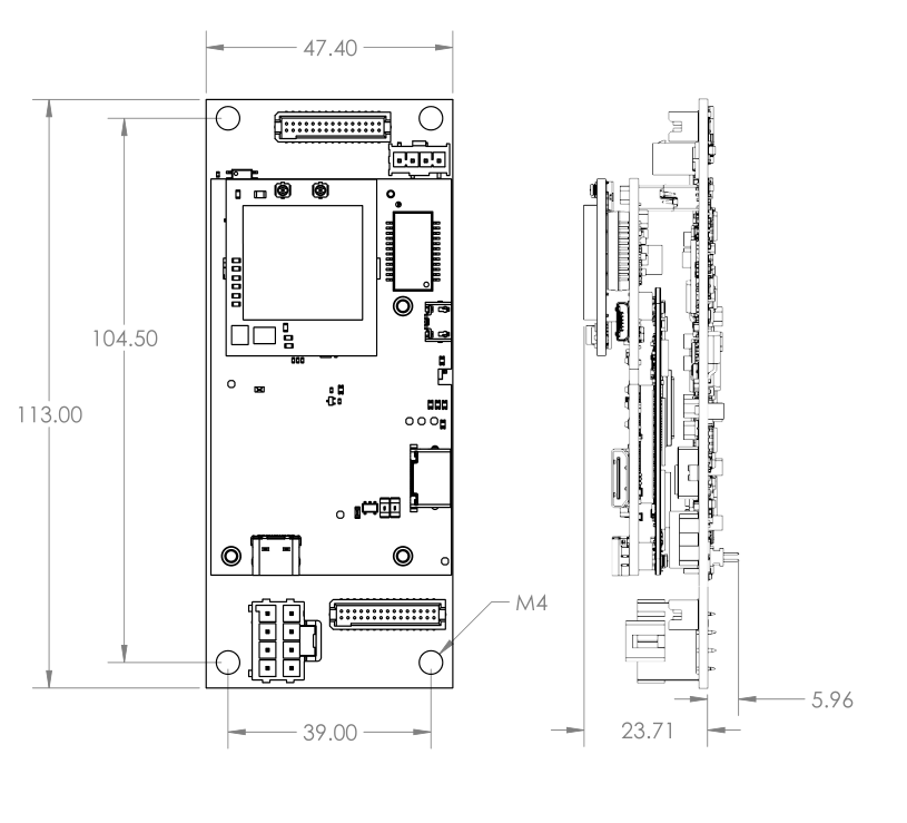
Color legend: C1 – 8 Pin header, C2 – 30 Pin header, C3 – 4 Pin header, C4 – 30 Pin header, Internal pin. Current Version: 1.0
*All Dimensions in millimeters |
The FlexCase E 1.0 (see previous versions) and R (OEM SBC) are almost identical except for a change of connectors. The FlexCase E is intented for IP rated applications whereas the OEM version is more suited for custom integrations.
¹ Pro version only
² Volume orders only
| Connector Pin # | Function | Application Comment |
|---|---|---|
| Power | ||
| C1-1 | + Supply Voltage | 8-36V (Unswitched)ⓘ Measure Supply Voltage ⓘ Measure Current |
| C1-6 | Ignition Input |
On/Off Switch ⓘ Keep On |
| C1-2 | Ground | Grounds are common |
| C2-23 C4-29 |
Ground | Grounds are common |
| C1-5 C2-21 |
+5 Volt Supply |
For powering 5V components. 2A Max |
| +5V Supply Enable | Set to enable +5V EXT | |
| Sensors | ||
| IMU | ConfigurableMISO, MOSI, CLK, CS,Int1, Int2 | |
| Board Version | Analog Measurement | |
| Power Good | Digital Measurement | |
| Ignition | Digital Measurement | |
| Coms | ||
| MCU-MPU SPI ¹ | MCU (Typically Slave): MISO, MOSI, CLK, CS
MPU (Typically Master): MISO, MOSI, CLK, CS1 |
|
| MCU-MPU UART ¹ | MCU <-> MPU | |
| MPU-MPU GPIO 1 ¹ | MCU <-> MPU | |
| MPU-MPU GPIO 0 ¹ | MCU <-> MPU | |
| MPU Reset ¹ | ⚠ Set high for >200ms then release | |
| MPU Sleep ¹ | ⚠ User for low power applications | |
| MPU-IoT Coms | Nimbelink/Airgain Skywire Compatible | |
| UART ¹ | USB recommended DTR, MPU RX, MPU TX, CTS, RTS | |
| USB ¹ | USB | |
| VUSB Enable ¹ | Set to enable USB communication | |
| Reset ¹ | Digital Output. Set to enable. | |
| ON/OFF Enable ¹ | Digital Output. Set to enable. | |
| Ref Voltage Power ¹ | Digital Output. Set to enable. | |
| Status ¹ | Digital Measurement | |
| CAN | ||
| C4-23 C1-3 |
MCU CAN0 High | FD capable |
| C4-21 C1-7 |
MCU CAN0 Low | FD capable |
| MCU CAN0 Enable | Set to enable CANbus | |
| C4-19 C1-4 |
MCU CAN1 High | FD capable |
| C4-17 C1-8 |
MCU CAN1 Low | FD capable |
| MCU CAN1 Enable | Set to enable CANbus | |
| C2-22 | MCU CAN2 High | FD capable |
| C2-24 | MCU CAN2 Low | FD capable |
| MCU CAN2 Enable | Set to enable CANbus | |
| C2-18 | MCU CAN3 High | FD capable |
| C2-20 | MCU CAN3 Low | FD capable |
| MCU CAN3 Enable | Set to enable CANbus | |
| LIN | ||
| C4-25 | MCU LIN Out | RX, TX,ENABLE |
| Ethernet | ||
| C2-1 | MPU MX1 Positive ¹ | T568B Orange White, RJ45 pin 1 |
| C2-8 | MPU MX1 Negative ¹ | T568B Orange, RJ45 pin 2 |
| C2-5 | MPU MX2 Positive ¹ | T568B Green White, RJ45 pin 3 |
| C2-10 | MPU MX3 Positive ¹ | T568B Blue, RJ45 pin 4 |
| C2-12 | MPU MX3 Negative ¹ | T568B Blue White, RJ45 pin 5 |
| C2-7 | MPU MX2 Negative ¹ | T568B Green, RJ45 pin 6 |
| C2-9 | MPU MX4 Positive ¹ | T568B Brown White, RJ45 pin 7 |
| C2-11 | MPU MX4 Negative ¹ | T568B Brown, RJ45 pin 8 |
| USB | ||
| C2-17 | USB 1 Data Positive ¹ | USB 2.0 Data Positive |
| C2-19 | USB 1 Data Negative ¹ | USB 2.0 Data Negative |
| USB 2 ¹ | USB 2.0 Available on via USB C connector | |
| HDMI | ||
| HDMI2.0 ¹ | HDMI 2.0 Available on via Mini HDMI connector | |
| RS | ||
| C2-16 | RS 232 TX ¹ | |
| C2-14 | RS 232 RX ¹ | |
| C2-13 | RS 485 A ¹ | |
| C2-15 | RS 485 B ¹ | |
| Digital Outputs (DO) |
||
| Bank 1 | ||
| Digital Output Enable | Set to enable Digital Outputs | |
| C2-29 | High Side Supply | Supplies DO 1 – 4 |
| C2-26 | MCU Digital Output 1 | High Side (DO/PWM) Low Side (DO/PWM) |
| C2-28 | MCU Digital Output 2 | High Side (DO/PWM) Low Side (DO/PWM) |
| C2-30 | MCU Digital Output 3 | High Side (DO/PWM) Low Side (DO/PWM) |
| C2-25 | MCU Digital Output 4 | High Side (DO/PWM) Low Side (DO/PWM) |
| Bank 2 | ||
| Digital Output Enable | Set to enable Digital Outputs | |
| C4-2 | High Side Supply | Supplies DO 5 – 8 |
| C4-6 | MCU Digital Output 5 | High Side (DO/PWM) Low Side (DO/PWM) |
| C4-1 | MCU Digital Output 6 | High Side (DO/PWM) Low Side (DO/PWM) |
| C4-3 | MCU Digital Output 7 | High Side (DO/PWM) Low Side (DO/PWM) |
| C4-4 | MCU Digital Output 8 | High Side (DO/PWM) Low Side (DO/PWM) |
| Digital Inputs (DI) |
||
| Digital Input Enable | Set high to enable Digital Input Pull Ups | |
| C1-8 | MCU Digital Input 1 | DI /PWM |
| C1-10 | MCU Digital Input 2 | DI /PWM |
| C1-12 | MCU Digital Input 3 | DI /PWM |
| C1-14 | MCU Digital Input 4 | DI /PWM |
| C1-16 | MCU Digital Input 5 | DI /PWM |
| C1-18 | MCU Digital Input 6 | DI /PWM |
| C1-20 | MCU Digital Input 7 | DI /PWM |
| C1-22 | MCU Digital Input 8 | DI /PWM |
| C1-24 | MCU Digital Input 9 | DI /PWM |
| C1-26 | MCU Digital Input 10 | DI /PWM |
| C1-28 | MCU Digital Input 11 | DI /PWM |
| C1-30 | MCU Digital Input 12 | DI /PWM |
| Analog Input (AIn) |
||
| C4-5 | MCU Analog Input 1 | 0-36V Configurable |
| C4-7 | MCU Analog Input 2 | 0-36V Configurable |
| C4-9 | MCU Analog Input 3 | 0-36V Configurable |
| C4-11 | MCU Analog Input 4 | 0-36V Configurable |
| C4-13 | MCU Analog Input 5 | 0-36V Configurable |
| C4-15 | MCU Analog Input 6 | 0-36V Configurable |
| C3-3 | MCU Analog Diff 1 High ² | 500mV Difference. High voltage tolerant. |
| C3-4 | MCU Analog Diff 1 Low ² | 500mV Difference. High voltage tolerant. |
| C3-1 | MCU Analog Diff 2 High ² | 500mV Difference. High voltage tolerant. |
| C3-2 | MCU Analog Diff 2 Low ² | 500mV Difference. High voltage tolerant. |
| RESERVED Board to board ² |
Available for volume orders. | |
| GPIO Reserved | GPIO1, GPIO2, GPIO3, GPIO4, GPIO5, GPIO6 | |
| Analog Input Reserved | AIN0, AIN1, AIN2, AIN3, AIN4 | |
| UART Reserved | RX, TX | |
| I2C Reserved | SCL, SDA | |
| SPI Reserved | SIN, SOUT, CLK, CS0, CS1 |
